
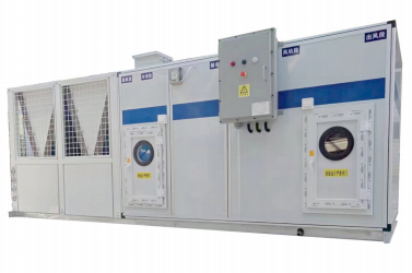
整体式多功能屋顶式机组
Product Category:
Keywords:
一、产品概述
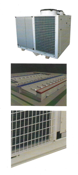
屋顶式空调机组是集冷(热)源和空气处理为-体的中央空调产品。该产品为全空气系统,通过制冷系统、控制系统和各种空气处理功能段的组合完成制冷、制(加)热、除湿、加湿、消声、空气净化、输送新风等功能。利用制冷系统中的换热器使制冷剂与空气直接进行热湿交换,没有中间换热介质二次交换带来的能量损失。无需循环水泵、冷却水塔、水管和专用机房等配套设备和设施,因此工程造价降低,安装工期短,室内无漏水之虞。机组安装于屋顶、室外庭院,无需机房,大大提高了建筑的使用率。该产品非常适用于体育馆、会展中心、影剧晥、会议室、场、机场候机厅、车站候车厅等舒适性空气调节系统,也可广泛应用干医药、电子、食品、机械、纺织等行业的工艺性空调系统
二、产品特点
屋顶式空调机组是我司重点打造的拳头产品,通过多年不断改进,机组系列更为完善,具有能效比高,低噪声,高静压,控制精度高,安全可靠以,振动小,防腐蚀程度高,帝封性能好,防雨防尘性能好,且具有安装方便,外型美观等特点,可方便地引入新风而无需专门的新风机和新风管,充分淡足室内空气品质的高要求,广泛适用于不便水系统安装和水资源缺乏地区的中央空调系统中。
|
规格齐全 机组品种规格齐全,有单冷型、冷暖型、热泵型、全新风型、洁净型等系列,可选各种功能段,可方便实现制冷、制热、加湿、除湿、再热、空气化、消声以及新风节能等多种功能,新风而无需专门的新风机和新区管,充分满足室内空气品质的高要求。广泛适用于不便水系统安装和水资源缺乏地区的中央空调系统中。 |
节省空间 机组设计为屋面 、室外庭院露天安装使用,具有防太阳暴晒 、防锈蚀 、防 暴雨等性能,无需专用机房,不占用室内有效空间。 |
|
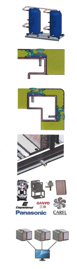
过冷设计 机组冷凝器底部设计过冷回路,制冷时增大制冷剂液体过冷度,提高冷量 和效率,更有效解决了制热时盘管底部结冰化霜不净的难题。 |
|
多能级控制 压缩机并联+热气旁通实现多能级追节,避免压缩机频紧后停,延长机组使F |
低漏风率 采用阶梯型多重密封结构及不间断无缝弹性体密封面两大技术保证机组在 |
|
不锈钢整体框架 框架采用钢、铝复合结构型材设计:强度比常规铝合金框架高83.7%,比常规钢框架结构高63.9%兼具铝合金框架高精度、美观的优点,1000Pa时箱体变形量0.68mm/m; 2500Pa 时,箱体变形量1,55mm/m,远优于国标要求1000Pa时箱体变形量<4mm/m的要求,达到欧标《EN1886-20078中最高D1等级。 |
|
不锈钢整体水盘 机组蒸发段整体水盘倾角设计,属于式盘水,排水口最低点,冷凝水快速流出,不积水,且保温性能佳,强度高。 |
|
品牌配件 机组的压缩机 、电子膨胀阀 、换热器 、离心风机 、轴流风机 、加湿器 、电 加热 、 电气元件等关键部件均选用国际或国内知名品牌的产品, 确保机组 质量稳定,运行节能安全可靠。 |
|
完备的机组控制 采用工业级微电脑控制,具有强大的运算能力, 对机组的各种运行参数能进 行实时监控和分析,使机组始终处于最佳运行状态,还具备远程通讯等功能。 |
三、产品应用指南
名义工况
| 工况名称 | 室内侧 | 室外侧 | ||
| 干球温度℃ | 温球温度℃ | 干球温度℃ | 温球温度℃ | |
| 标况制冷工况 | 27 | 19 | 35 | 24 |
| 标况制热工况 | 20 | < 15 | 7 | 6 |
| 电加热制热工况 | 20 | < 15 | ||
| 恒温恒湿工况 | 23 | 17 | 35 | 24 |
| 全新风标况制冷工况 | 35 | 28 | 35 | 28 |
| 全新风标况制热工况 | 7 | 6 | 7 | 6 |
四、产品种类及选型
新推整体式多功能屋顶式空调机组标准产品有冷暖(热泉)型、单冷尘、冷暖(加热)型、洁净型、全新风型共5个系分
25kw~200kW
制热量范围:26kw~210kw
风量范围:2000m/h~40000m/h
机外静压范园:25Pa~1000Pa
整体式多功能屋顶机选型指导表
| 可选配置名称 | 可选配置 | |
| 机组特征可 | 选洁净型 ( J)、 普通型 ( 略 ) | |
| 机组特征1 | 全新风型 ( X ) 、 混合风型 ( M)、 回风型 ( 略 ) | |
| 机组形式2 | 热泵型 ( R)、 单冷型 ( L) | |
| 加热方式 | 可选电加热 ( D)、蒸汽加热 ( Q)、热水加热 ( S) | |
| 加湿方式 | 可选干蒸汽加湿 ( Z)、 电极加热 ( J)、 湿膜加湿 ( M) | |
| 制冷剂 | 可选R410A(C)、 R32(E) | |
| 名义制冷量 | KW | 参考技术参数表 ( 制冷量范围 : 25kw- 200kw) |
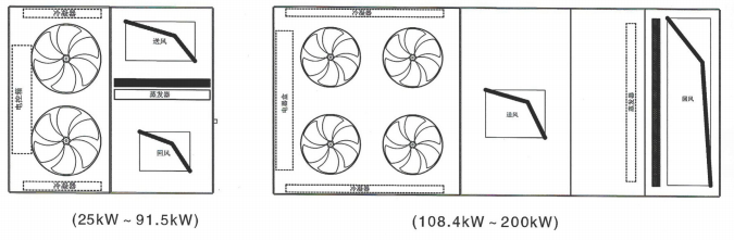
| 送、 回风方式 | 侧送测回 ( 略 ) 、 下送下回 ( A ) 、 其它 ( B ) | |
| 机外静压值 | 25pa - 1000pa | |
侧送侧回
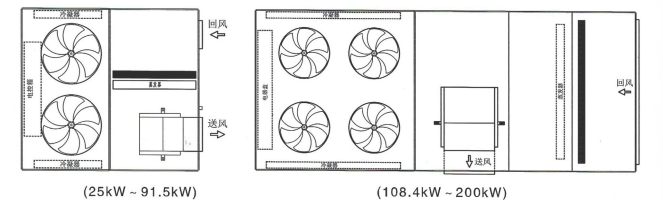
下送下回
请按照机组型号表示方法写出您需要的机组型号 :
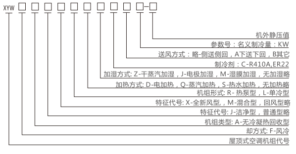
示例:
(1)名义制冷量为55kW,回风型热泵机组,配置辅助电加热,制冷剂R410A,过滤等级G3 +F5,送风方式为侧送侧回,机外静压300Pa的整体式屋顶机型号应为:XYWFAJRDC55-300.
(2)名义制冷量为90kW,全新风冷暖(加热)型机组,制冷剂R410A,过忠等级G3,湿膜加湿,送风方式为下送下回,机外静压350Pa的整体式屋顶机型号应为:XYWFAXRMCA90-350。
五、订货注意事项
(1)机组"技术参数表"提供了屋顶式空调机组在额定工况下的制冷量、制热量,如果使用工况与额定工况不同,应按照“变工况性能修正系数予以修正:
(2)整个空调系统的风管阻力应与机外静压相匹配,如果所选机外静压或风量和"技术参数表”中不同,请在订货合同中注明;(3)机组出厂自带冷媒,现场无需充注:
(4)全新风型机组不承担空调区域的房间负荷,采用送风温度控制机组的能级;
(5)如需预制机组基础,请參考"机组基础图"制作:
(6)为了使机组能够更好的为您服务,请您在订货前注明机组的使用场所和使用季节,我们将有机会为您提供更为稳定可靠的控制系统:(7)本公司产品在安装调试时,可向我公司提出技术支持:
(8)本公司遵循不断完善产品的原则,对产品规格、性能、材料的部分改进或许难以通知阁下,敬请谅解。请与我公司保持联系以索取最新资料。
机组订货时需提供信息 :
| 名称 | 说明 |
| 机组型号 | 按机组 选型指导表编制 |
| 机组的使用场所 | 按机组的使用场所不同 , 配置不同 |
客户可根据具体要求(冷/热量、风量、机外静压等具体条件)參照样本参数进行产品选型,样本范围外风量、冷量及机外静压及其它功能段机组,需非标选型,您可与总公司或各地分公司联系。
六、机组技术参数
热泵型、 单冷型 ( 性能参数表 1 )
| 机组型号 | XYWFARC28-250 | XYWFARC35-250 | XYWFARC45-320 | XYWFARC55-320 | ||
| XYWFALC28-250 | XYWFALC35-250 | XYWFALC45-320 | XYWFALC55-320 | |||
| 性能 | 使用电源 | 3/N/PE AC 380/220V 50Hz | ||||
| 制冷量1* | KW | 28.5 | 35.2 | 44.2 | 55.1 | |
| 制冷量2* | KW | 30.8 | 37.2 | 47.5 | 57.8 | |
| 名义制冷输入功率 | KW | 9.8 | 12.0 | 15.0 | 18.0 | |
| 名义制热输入功率 | KW | 10.4 | 12.6 | 15.5 | 19.7 | |
| 温度控制灵敏度3* | ℃ | +2 | ||||
| 容量控制 | % | 0/50/100 | 0/50/100 | 0/50/100 | 0/50/100 | |
| 压缩机 | 类型 | 全封闭涡旋并联压缩机 | ||||
| 数量 | 个 | 2 | 2 | 2 | 2 | |
| 制冷剂 | 使用工质 | R410A | ||||
| 控制方式 | 电子膨胀阀 | |||||
| 充注量 | kg | 7 | 7 | 12.5 | 14 | |
| 送风机 | 类型 | 离心式 | ||||
| 驱动方式 | 皮带驱动 | |||||
| 风量 | m3/h | 5800 | 6500 | |||
| 机外静压 | pa | 250 | 250 | 320 | 320 | |
| 电机功率 | KW | 2.2 | 2.2 | 3 | 3 | |
| 冷凝风机机 | 类型 | 高效轴流风机 | ||||
| 数量 | 个 | 2 | 2 | 2 | 2 | |
| 风量 | m3/h | 7000x2 | 7000x2 | 1 1 o00x2 | 1 1 600x2 | |
| 输入功率 | KW | 0 . 4x2 | 0 . 4x2 | 0 . 7x2 | 0 . 9x2 | |
| 电加热 | 辅助加热量4* | KW | 9 | 12 | 15 | 18 |
| 两器 | 类型 | 高效内螺纹铜管套铝翅片 | ||||
| 过滤器 | 类型及等级 | 板式G3 | ||||
| 电气参数 无电加热 |
最大运行电流 | A | 26.68 | 26.68 | 26.68 | 26.68 |
| 建议电源线径 | 2 | 6 | 10 | 16 | 16 | |
| 电气参数 有电加热 |
最大运行电流 | A | 40.32 | 48.26 | 61.57 | 71.25 |
| 建议电源线径 | 2 | 16 | 25 | 25 | 38 | |
| 机组尺寸 | 长x宽x高 | 1870x1700x1770 | 1870x1700x1770 | 2375x2000x1970 | 2375x2000x2000 | |
| 机组重量 | kg | 700 | 710 | 986 | 1042 | |
| 噪音 | dB(A) | 64 | 64 | 66 | 68 | |
备注:
1、 制冷量标定工况: OA: DB(A)=35°C; RA: DB(A)=27°C,WB=19°C;2、制热量标定工况: OA: DB(A)=7°C,WB=6°C; RA: DB(A)=20°C;3、热泵型、单冷型控制对象为机组回风温度;
辅助加热量为选配项,当所需辅助加热量与样本不一致时,可与我司技术人员联系;4.5、 非标产品样本性能参数与铭牌不一致,以铭牌参数为准。
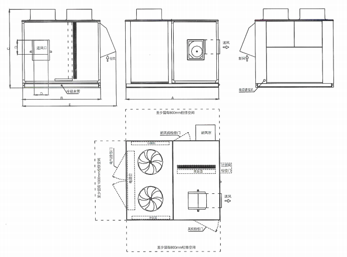
七、机组外型图
热泵型、 单冷型、 洁净式热泵型、 洁净式单冷型
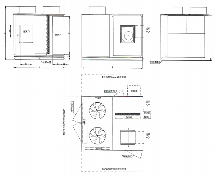
| 机组系列 | 机组制冷量 | A | B | C | D | E | F | G | H |
| XYWFARC XYWFALC XYWFAJRC XYWFAJLC |
28(kw) | 1870 | 1700 | 1770 | 361 | 300 | 1228 | 86 | 206 |
| 35(kw) | 1870 | 1700 | 1770 | 361 | 300 | 1228 | 86 | 206 | |
| 45(kw) | 2375 | 2000 | 1970 | 453 | 400 | 1428 | 86 | 206 | |
| 55(kw) | 2375 | 2000 | 2000 | 453 | 400 | 1428 | 86 | 206 | |
| 70(kw) | 2900 | 2300 | 2200 | 569 | 450 | 1628 | 86 | 206 | |
| 90(kw) | 2900 | 2300 | 2200 | 569 | 450 | 1628 | 86 | 206 |
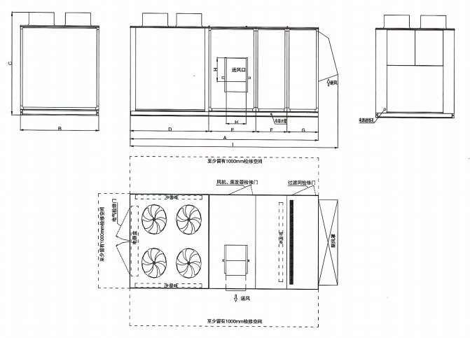
热泵型、单冷型、洁净式热泵型、洁净式单冷型
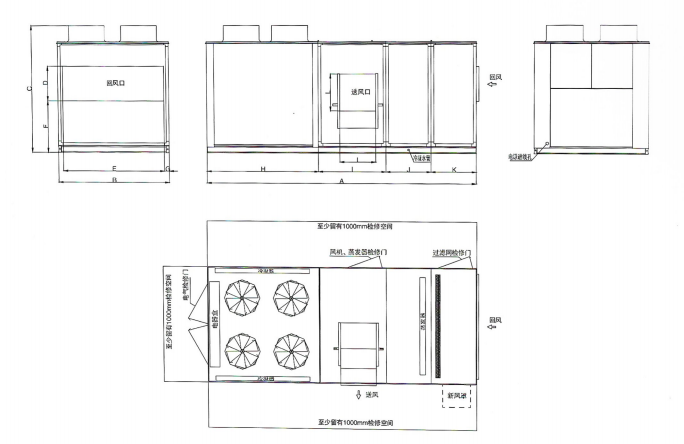
| 机组系列 | 机组制冷量 | A | B | C | D | E | F | G | H | I | J | K | L |
| XYWFARC XYWFALC XYWFAJRC XYWFAJLC |
110(kw) | 4800 | 2000 | 2200 | 600 | 1828 | 900 | 86 | 2000 | 1200 | 800 | 800 | 638 |
| 125(kw) | 4800 | 2000 | 2200 | 600 | 1828 | 900 | 86 | 2000 | 1200 | 800 | 800 | 638 | |
| 140(kw) | 5300 | 2200 | 2316 | 715 | 2080 | 900 | 86 | 2300 | 1400 | 800 | 800 | 801 | |
| 180(kw) | 5300 | 2200 | 2316 | 716 | 2080 | 900 | 86 | 2300 | 1400 | 800 | 800 | 801 |
全新风热泵型、 全新风单冷型、 全新风洁净式热泵型、 全新风洁净式单冷型
| 机组系列 | 机组制冷量 | A | B | C | D | E | F | G | H | I |
| XYWFAXRC XYWFAXLC XYWFAXJRC XYWFAXJLC |
110(kw) | 4800 | 2000 | 2200 | 2000 | 1200 | 800 | 800 | 507 | 5300 |
| 125(kw) | 4800 | 2000 | 2200 | 2000 | 1200 | 800 | 800 | 507 | 5300 | |
| 140(kw) | 5300 | 2200 | 2316 | 2300 | 1400 | 800 | 800 | 569 | 5300 | |
| 180(kw) | 5300 | 2200 | 2316 | 2300 | 1400 | 800 | 800 | 569 | 5300 |
全新风热泵型、 全新风单冷型、 全新风洁净式热泵型、 全新风洁净式单冷型
| 机组系列 | 机组制冷量 | A | B | C | D | E | F | G | H | J |
| XYWFAXRC XYWFAXLC XYWFAXJRC XYWFAXJLC |
110(kw) | 4800 | 2000 | 2200 | 2000 | 1200 | 800 | 800 | 507 | 5300 |
| 125(kw) | 4800 | 2000 | 2200 | 2000 | 1200 | 800 | 800 | 507 | 5300 | |
| 140(kw) | 5300 | 2200 | 2316 | 2300 | 1400 | 800 | 800 | 569 | 5300 | |
| 180(kw) | 5300 | 2200 | 2316 | 2300 | 1400 | 800 | 800 | 569 | 5300 |
全新风热泵型、全新风单冷型、全新风洁净式热泵型、全新风洁净式单冷型
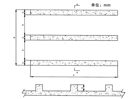
| 机组系列 | 机组制冷量 | A | B | C | D | E |
| XYWFARC XYWFALC XYWFAJRC XYWFAJ LC XYWFAXRC XYWFAXLC XYWFAXJRC |
28(kw) | 2100 | 1900 | 200 | 650 | 250 |
| 35(kw) | 2100 | 1900 | 200 | 650 | 250 | |
| 45(kw) | 2600 | 2200 | 200 | 800 | 250 | |
| 55(kw) | 2600 | 2200 | 200 | 800 | 250 | |
| 70(kw) | 3100 | 2500 | 200 | 950 | 250 | |
| 90(kw) | 3100 | 2500 | 200 | 950 | 250 | |
| XYWFAXJLC | 110(kw) | 5000 | 2200 | 200 | 800 | 250 |
| 125(kw) | 5000 | 2200 | 200 | 800 | 250 | |
| 140(kw) | 5500 | 2400 | 200 | 950 | 250 | |
| 180(kw) | 5500 | 2400 | 200 | 950 | 250 |
基础说明:
a.机组基础为混凝土;
b.定要在混凝土达到规定强度后才能将机组安放在基础上;c.基础表面应用水平仪找平,安装前必须核对及检查基础尺寸;.
注:
下出风机组的基础需要结合安装位置和机组外形综合考虑(具体项目需要具体出方案),安装时需要注意防雨水的设计。
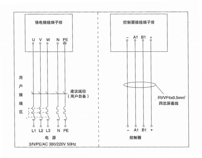
九、客户接线
电气概述
请仔细阅读随机提供的电气接线图和使用说明书。检査电源电压是否与机组铭牌上规定的相一致,检査电源导线。所有供电线路的安装、连接、布置应按照国家相关电气规范进行要求所有供电导线均为铜导线。控制电缆线与动力线要分开敷设并套护管,以防止动力线对控制电缆(线)产生干扰。根据机组实际安装位置,应考虑避雷条件。
注意:
(1)机组必须可靠接地。
(2)采用三相电源的机组,--旦投入运行,必须保持其电源相序不变。
控制器(线控器)安装
线控器可以采用标准86型底盒直接在墙面安装,线控器与控制器的连RWP4X0.5mm2(四芯电缆)安装时可考虑预埋,需要合里选择安装位置。
控制器(线控器)安装
十、变工况性能修正系数
当机组的使用工况与标准工况不同时 , 需对制冷量值进行如下修正: 不同工况下制冷量修正系数(全新风机组除外) :
| 室内进风温度℃ | 室外进风温度℃ | |||||||||
| 干球 | 湿球 | 25 | 30 | 35 | 40 | 45 | ||||
| 20 | 16 | 0.92 | 0.88 | 0.85 | 0.83 | 0.79 | ||||
| 23 | 17 | 0.98 | 0.94 | 0.9 | 0.88 | 0.83 | ||||
| 25 | 18 | 1.06 | 0.99 | 0.97 | 0.91 | 0.88 | ||||
| 27 | 19 | 1.11 | 1.05 | 1 | 0.95 | 0.91 | ||||
| 28 | 20 | 1.13 | 1.08 | 1.03 | 0.97 | 0.94 | ||||
| 30 | 22 | 1.12 | 1.12 | 1.08 | 1.03 | 0.99 | ||||
| 室内进风温度℃ | 室外进风温度℃ | |||||||||
| 干球 | 湿球 | 25 | 30 | 35 | 40 | 45 | ||||
| 25 | 18 | 0.94 | ||||||||
| 30 | 22 | 0.96 | ||||||||
| 35 | 28 | 1 | ||||||||
| 40 | 32 | 1.01 | ||||||||
| 43 | 35 | 1.02 | ||||||||
| 室内进风温度℃ | 室外进风温 度℃ | |||||||||
| 干球 | - 5/ - 5 5 | 2/1 | 7/6 | 10/8 5 | 15/13 | |||||
| 0.79 | 0.94 | 1.03 | 1.14 | 1.29 | ||||||
| 18 | 0.78 | 0.93 | 1.02 | 1.12 | 1.27 | |||||
| 20 | 0.77 | 0.92 | 1 | 1.11 | 1.25 | |||||
| 21 | 0.76 | 0.99 | 1.08 | 1.22 | ||||||
| 22 | 0.76 | 0.89 | 0.99 | 1.08 | 1.19 | |||||
| 24 | 0.75 | 0.89 | 098 | 107 | 1.18 | |||||
| 室内进风温度℃ | 室外进风温 度℃ | |||||||||
| 干球 | - 5/ - 5 5 | 2/1 | 7/6 | 10/8 5 | 15/13 | |||||
| 5 | 0.89 | |||||||||
| 2 | 0.93 | |||||||||
| 7 | 1 | |||||||||
| 1.02 | ||||||||||
| 15 | 1.03 | |||||||||
十一、机组安装技术要求
空调机组安装前应仔细阅读下列说明 , 以避免对机组造成不必要的损害: 一般要求
(1)机组在搬运移动时应尽量保持水平,切勿倾斜30度以上,从机组底支架吊装孔吊装,吊具,上部应有支撑杆以免伤及设备(2)机组可安装于屋顶或屋外庭院,且支撑面须有定够的强度,能承受机组运行时的重量;
(3)机组不应安装在有腐蚀性气体和湿度大的场合,
(4)机组安装场合须留有足够的空间以供散热和方便维修保养人员进出;
(5)机组就位时;应在机组下安装合适的减振装置;安装机组的屋面、地坪应有足够的强度与水平度,以支撑机组。安装不正确会带来额外的噪声与振动;
(6)机组整体式出厂,冷媒已充注完毕,现场无需二次加注;
(7)电源接线须符合当地的规定,电压波动不得超过额定电压10%,三相电源相间不平衡度在2%以内,电源线应单独布线,不得与其他线路共
用:
(8)与机组连接的风管和水管等重量不能由机组承担;
(9)空调机组外壳应可靠接地;
(10)根据机组实际安装位置的高度,应考虑避雷,
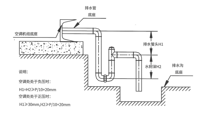
存水弯安装
机组空气处理段蒸发器处于负压,为确保凝结水顺利通畅的排出,凝结水管需设置存水弯。其水封高度差可参考水封示意:图,同时:凝结水管应保持畅通,保证排水坡度>0.005,存水弯制作如下图:
Next


Product Inquiry
*Note: Please fill in the information accurately and keep the communication open. We will contact you as soon as possible.
Online Message
Thank you for your valuable opinions and suggestions. We will reply to you as soon as possible!
New Super-Aire Equipment Ltd.
Address: Laocun Industrial Zone, Sanle Road, Lecong Town, Shunde District, Foshan City, Guangdong Province
Tel: 0757-28850303 / 0757-28850330
Tel: 0757-28862319 / 0757-28831625
Fax: 0757-2886 9823
Email: xykt@xykt.com.cn

Follow Douyin account

Mobile version


Copyright © 2025 New Super-Aire Equipment Ltd. All rights reserved