Screw chiller/heat pump unit
Product Category:
Keywords:
Appearance Introduction
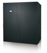
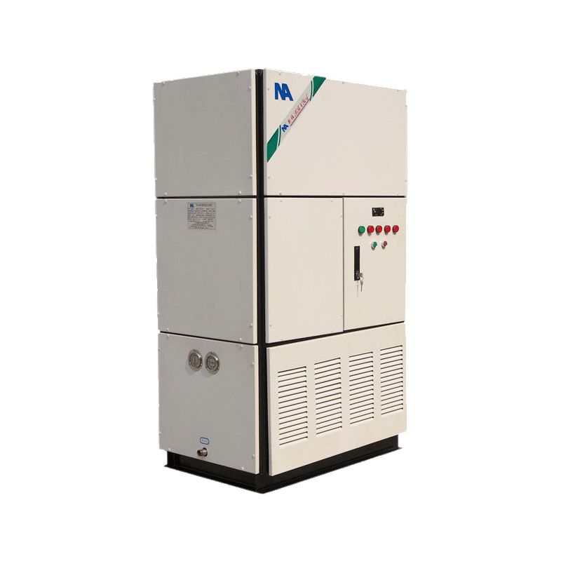
The appearance of the Xinya DX direct expansion room-level precision air conditioner indoor unit is shown in Figure 1-1.
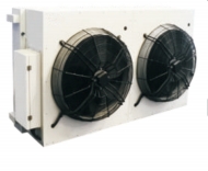
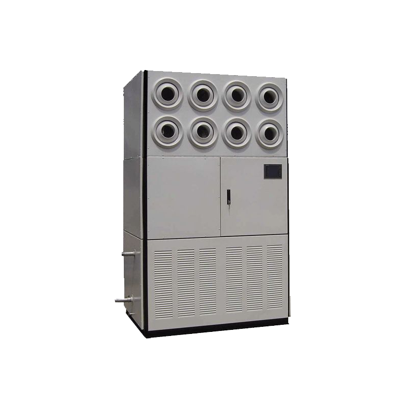
The appearance of the Xinya DX direct expansion room-level precision air conditioner outdoor unit is shown in Figure 1-2.
1 | 2 | 3 | 4 | 5 | 6 | 7 | 8 | 9 | 10 |
HM | 070 | A | X | P | E | K | B | M | 0 |
Indoor Unit Model Description
Serial Number | Category | Code | Description |
1 | Series Name | HM | Xinya DX Series Room-Dedicated Air Conditioner |
2 | Cooling Capacity | 070 | Cooling Capacity Level |
3 | Cooling Method | A | Air Cooling |
W | Water Cooling | ||
One | Other | ||
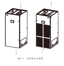
4 | Air Delivery Method | X | Air, Down-blowing air delivery |
D | Down-blowing | ||
U | Up-blowing (front blowing can be achieved with optional air hood) | ||
5 | Function | B | Cooling Function |
R | Cooling and Heating Function | ||
H | Cooling and Humidification Function | ||
P | Cooling, Heating, and Humidification Function | ||
6 | Fan Type | E | EC Fan |
7 | System Configuration | J | R410A Single System (Standard for single system, 25~45kW) |
K | R410A Dual System (Standard for dual system, 50~90kW) | ||
One | Other | ||
8 | Pipe Outlet Method | L | Left Pipe Outlet (Standard, except for dual-system units) |
R | Right Pipe Outlet | ||
B | Left module left pipe outlet, right module right pipe outlet (Standard, dual-system units) | ||
9 | Power System | M | 3N+PE~380V, 50Hz (Standard) |
Q | 3N+PE~380V, 60Hz | ||
One | Other | ||
10 | Special Functions | 0 | None (Standard) |
1 | Condensation Pump Included | ||
One | Other |
I. Product Introduction
Outdoor Unit Model Description
Table 1-2 Outdoor Unit Model Description.
1 | 2 | 3 | 4 | 5 | 6 |
SW | 50 | N | P | H | M |
Serial Number | Category | Code | Description |
1 | Series Name | SW | Machine Room Dedicated Air Conditioner Outdoor Unit |
2 | Heat Exchange Capacity | 50 | Heat Exchange Capacity Level |
3 | Compressor Location | N | Compressor Located Indoors |
4 | Heat Exchanger Name | P | Flat Plate Type |
V | V-shaped Centralized Type | ||
5 | Refrigerant | H | Refrigerant R410A (Standard) |
6 | Power System | M | 3+PE~380V, 50Hz (Standard) |
Q | 3+PE~380V, 60Hz | ||
One | Other |
II. Product Features
Diverse Forms
According to the air delivery method, it can be divided into up-blowing and down-blowing forms, and the diverse forms meet the requirements of different installation and usage environments. Wide range of cooling capacity
Cooling capacity 25kW~110kW, can be freely matched to suit large, medium, and small machine rooms. Precise control
Brightness accuracy can be controlled within ±1°C, humidity accuracy can be controlled within ±5%RH. High energy efficiency
Using high-efficiency scroll compressors, high-efficiency V/IA finned heat exchangers, finely designed liquid distributors, and more reasonable internal layout
The air flow field inside the air conditioner is more uniform, and the refrigerant distribution is more reasonable, which greatly improves the heat exchange efficiency of the heat exchanger, making the air conditioning unit achieve high efficiency and energy saving, convenient and durable
Unique modular frame, compact structure, small overall size, stable and strong, easy to disassemble, can meet the requirements of transportation under extreme conditions; using insulation cotton, the insulation performance inside the machine body is good; single-door and double-door structures have high versatility, greatly reducing the specifications of easily damaged parts (such as air filters, etc.). Infrared humidification
Using advanced infrared humidification technology, effectively reducing the dependence of the humidifier on water quality, humidity control is fast and accurate. Environmentally friendly refrigerant
采用先进的红外加湿技术,有效地减少了加湿器对水质的依赖性,湿度控制快速、准确。环保冷媒
Adapting to international standards and environmental regulations for refrigerants, it uses the environmentally friendly refrigerant R410A. Multiple protection features, including comprehensive diagnostics and automatic alarm functions, effectively prevent malfunctions, quickly locate fault points, provide all-around protection for the unit, and significantly extend the service life of the air conditioning unit.
Easy Maintenance
The entire unit uses a full front-opening design, allowing maintenance of all components from the front, saving space.
Indoor Unit
The indoor unit mainly consists of a compressor, evaporator, expansion valve, fan, sight glass, dryer filter, infrared humidifier, PTC heater, safety control device, air filter, and other components. Compressor
The compressor uses a high-efficiency scroll compressor (as shown in Figure 1-3), which features low vibration, low noise, and high reliability. Evaporator
A high-efficiency VIA finned evaporator (as shown in Figure 1-4) is used. The fins are hydrophilic slotted fins, and the inner tubes are copper tubes with internal threads, resulting in higher heat exchange efficiency. Appropriate distributors are designed and verified for specific models to ensure uniform refrigerant distribution in each circuit, greatly improving the efficiency of the heat exchanger.
Outdoor Unit
The throttling device is equipped with a high-precision electronic expansion valve control (as shown in Figure 1-5), and the online expert algorithm precisely controls the refrigerant flow, making the operation more efficient and the system safer and more stable.
Dryer Filter The dryer filter (as shown in Figure 1-7) can effectively remove moisture from the refrigeration system within a short period and filter impurities generated during long-term operation, ensuring normal system operation.
Fan A snail-less centrifugal fan (as shown in Figure 1-6) is used, which features large air volume, long air delivery distance, easy maintenance, high reliability, and stepless speed regulation. The advanced fan fault detection system can automatically detect reduced air volume caused by abnormal fan operation, stop heating or warming operations, and issue an alarm signal.
Infrared Humidifier
The infrared humidifier (as shown in Figure 1-8) features microprocessor control and a simple structure, making it easy to disassemble, clean, and maintain. High-strength ceramic tubes suspended above a stainless steel heating water pan emit infrared and far-infrared light, causing water molecules in the pan to absorb radiation and break free from surface tension within 5-6 seconds, evaporating in a pure state without any impurities. The use of an infrared humidifier reduces the system's dependence on water quality, and its automatic flushing function keeps the water pan cleaner.
Sight Glass
A window in the system circuit allows observation of the refrigerant state and detection of system moisture content. When the system moisture content exceeds the standard, the bottom color changes to the alarm zone color.
PTC Electric Heating
PTC electric heating (as shown in Figure 1-9) is used, which features safety, energy efficiency, rapid heating, and a wide range of operating ambient temperatures and voltages. Its heat output maintains the dry-bulb temperature of the machine room while compensating for the temperature drop caused by dehumidification. The low surface temperature of the PTC heating system prevents air ionization, thus extending its service life.
Safety Control Device Each refrigeration system is equipped with high-pressure, low-pressure, and exhaust temperature protection devices. When the compressor's exhaust pressure or exhaust temperature is too high, an emergency alarm is issued and protection is activated. When the compressor's suction pressure is too low to operate normally, an alarm signal is issued and protection is activated. Each fan is equipped with an overheat protection device. When the fan overheats, timely protection is provided. The filter clogging switch monitors the air conditioning unit's air system in real-time.
Air Filter
A standard air filter (as shown in Figure 1-10) is used, which is easy to replace. The filtration efficiency grade is G4 (EN779), with an average filtration efficiency of over 90%, effectively ensuring the cleanliness of the machine room.
Air-Cooled Outdoor Unit
Standard Type
It uses a corrugated fin-tube heat exchanger, which features high heat dissipation efficiency and easy cleaning and maintenance. The external rotor axial flow fan and unique "mirror knife" shaped metal blades have superior aerodynamic characteristics and high efficiency. The large diameter and eight-blade fan, combined with a specially designed guide vane, significantly reduces airflow noise. A high-performance three-phase motor customized for the base station's electrical environment has a wide applicable voltage range and high reliability. The advanced fan speed control system adjusts the output voltage by detecting the system's condensing pressure, thereby controlling the outdoor fan speed to match the system pressure with the heat load, effectively reducing fan noise and ensuring stable, reliable, and efficient system operation. The variable frequency speed-controlled outdoor fan supports a maximum adjustable range of 10%~100%, suitable for configurations in different temperature environments. Energy-saving type (optional) Based on the standard type, the energy efficiency ratio of the entire system is improved through unique design, making the entire unit more energy-efficient and efficient, while also meeting the requirements of high-temperature environments (+45°C~55°C).
Energy-Saving Type (Optional)
Based on the standard type, low-sliding components and electronic control antifreeze protection are added, allowing the entire system to operate normally at temperatures as low as -40°C. The microprocessor control system is designed to meet the special requirements of the machine room, featuring good stability, high control precision, and intelligence. The indoor unit's front door provides a true color touch screen (LED) control panel. The simple and easy-to-understand interface displays the current indoor temperature, humidity, set points, equipment (fan, compressor, cooling, heating, dehumidification, humidification, etc.) output percentage, and alarm status. Users can access and set various set points, event logs, graphical data, sensor data, and alarm settings from the main menu on the display screen. The LCD backlight uses an energy-saving design; when there is no operation for a certain period (factory setting is 5 minutes, configurable via the menu), the backlight turns off; the backlight turns on again when an operation is performed. The control system also supports multi-unit group control, intelligently realizing expansion, and multiple reserved interfaces can realize various control methods. The microprocessor controller panel is shown in Figure 1-11.
Control System
The user interface is clean and simple, with multi-level password protection to effectively prevent unauthorized access. The controller has power-off self-recovery and high/low voltage protection functions.
The operating time of each major component can be accurately understood through menu operation.
Expert-level fault diagnosis system, automatically displays current fault content, facilitating equipment maintenance by maintenance personnel. It can store 400 historical event records, recording messages, warnings, and alarms of three types of events. It is configured with an R5485 interface, and communication uses standard communication protocols.
Temperature setting; the temperature setting range is 18°C-32°C
Humidity setting; the humidity setting range is 40%RH-95%RH.
Alarm signal.
The microprocessor has audible and visual alarm functions. Standard alarm information includes high-temperature alarm, low-temperature alarm, high-humidity alarm, low-humidity alarm, system high-pressure alarm, system low-pressure alarm, filter clogging alarm, and other user-defined alarms with indicator light. The control system also supports multi-unit group control, intelligently realizing expansion. Multiple reserved interfaces can realize various control methods. The microprocessor controller panel is shown in Figure 1-11.
Optional parts
Top air supply hood
For top air supply systems, an optional matching top air supply hood is available to ensure uniform airflow. Extension component
For applications with long connecting pipes, extension components can be used. After the compressor stops, the extension component effectively prevents refrigerant backflow and accumulation, ensuring the normal start-up of the compressor next time, making the system safer and more reliable.
Waterless alarm; rope-type and single-point water leak detectors can provide alarm signals to the unit or an independent monitoring system, triggering the unit alarm and promptly shutting down the unit for timely processing.
Smoke detector
When the smoke detector detects smoke, it can immediately trigger the alarm system to shut down the unit. Fire detector
The fire detector monitors the return air temperature at the site. Once high temperature is encountered, it immediately shuts down the unit. High-efficiency air filter
High-efficiency air filters are suitable for use environments with higher cleanliness requirements.
Humidifier
The humidifier (Figure 1.12) is a built-in humidifier component of the air conditioner. It has a clean structure, is clean and noiseless, uses environmentally friendly organic wet-membrane materials, has excellent water absorption, high saturation efficiency, is lightweight, easy to produce, small in size, saves space, and is easy to disassemble, clean, and maintain. At the same time, it has a washing and filtering effect on the air, and can achieve clean, constant enthalpy humidification. During humidification operation, the humidifier body consumes no power, saving energy significantly. Note: Single-cooling models do not have heating humidification.
Indoor unit model | HM025A | HM030A | HM035A | HM040A | HM045A | HM050A |
Main power supply | 3N+PE~380V 50Hz | |||||
Indoor return air conditions: 24℃ DB/17℃ WB; Outdoor environmental conditions: (Air-cooled) 35℃ | ||||||
Cooling capacity - kW | 26.4 | 31.5 | 36.1 | 38.1 | 45.7 | 52.7 |
System cooling capacity - kW | 24.5 | 29.2 | 33.4 | 35.2 | 41.6 | 48.9 |
Compressor | ||||||
Number of units | 1 | 1 | 1 | 1 | 1 | 2 |
Indoor fan | ||||||
Fan circulation air volume - m³/h | 7500 | 9000 | 10500 | 11500 | 12000 | 15000 |
Parameters Number of units | 1 | 1 | 1 | 1 | 1 | 2 |
Electric heating performance parameters | ||||||
Heating capacity - kW | 6 | 6 | 6 | 6 | 6 | 9 |
Humidifier performance parameters | ||||||
Humidification capacity - kg/h | 4.5 | 4.5 | 4.5 | 4.5 | 4.5 | 6.5 |
Filter | ||||||
Filtration grade | G4 | |||||
Connecting pipe size specifications | ||||||
Liquid pipe - mm (welded) | 15.88 | 15.88 | 15.88 | 15.88 | 15.88 | 15.88 |
Gas pipe - mm (welded) | 22 | 22 | 22 | 22 | 22 | 22 |
Humidifier inlet pipe (internal thread) | G1/2" | G1/2" | G1/2" | G1/2" | G1/2" | G1/2" |
Drain pipe OD - mm (tower + hose clamp) | 19 | 19 | 19 | 19 | 19 | 19 |
Indoor unit full-load current and power (with heating and humidification unit) | ||||||
Indoor unit full-load current - A | 32.12 | 38.2 | 41.05 | 41.05 | 48.97 | 59.74 |
Indoor unit full-load power - kW | 19.07 | 22.71 | 23.93 | 23.93 | 28.28 | 35.14 |
Indoor unit dimensions | ||||||
Unit width - mm | 900 | 900 | 900 | 900 | 900 | 1800 |
Unit depth - mm | 1000 | 1000 | 1000 | 1000 | 1000 | 1000 |
Unit height - mm | 1980 | 1980 | 1980 | 1980 | 1980 | 1980 |
Indoor unit weight | ||||||
Indoor unit static weight - kg | 355 | 370 | 375 | 380 | 390 | 665 |
Outdoor unit model | 1*SW40NP | 1*SW50NP | 1*SW50NP | 1*SW50NP | 1*SW70NP | 2*SW40NP |
Main power supply | 380V 3Ph 50Hz | |||||
Outdoor unit full-load current and power (indoor and outdoor units are separately powered) | ||||||
Outdoor unit full-load current - A | 2.9 | 4.7 | 4.7 | 4.7 | 5.8 | 2*2.9 |
Outdoor unit full-load power - kW | 1.06 | 1.8 | 1.8 | 1.8 | 2.1 | 2*1.06 |
Outdoor unit dimensions | ||||||
Unit width - mm | 1650 | 1650 | 1650 | 1650 | 2010 | 1650 |
Unit depth - mm | 1100 | 1100 | 1100 | 1100 | 1100 | 1100 |
Unit height - mm | 1150 | 1150 | 1150 | 1150 | 1150 | 1150 |
Outdoor unit weight | 158 | 168 | 168 | 168 | 210 | 2*158 |
Note:
1. The above indoor unit outlet static pressure is: top air supply 50Pa, bottom air supply 20Pa. Models with up to 200Pa can be customized.
2. The parameters in this table are for standard configuration normal temperature outdoor units.
3. If the required data is not listed in the table, please contact Xinya Air Conditioning.
4. Depending on project conditions, it supports separate power distribution for indoor and outdoor units, and also supports outdoor unit power being drawn from the indoor unit.
Indoor unit model | HM060A | HM070A | HM080A HM090A | HM100A | HM110A | ||
Main power supply | 3N+PE~380V 50Hz | ||||||
Indoor return air conditions: 24℃ DB/17℃ WB; Outdoor environmental conditions: (Air-cooled) 35℃ | |||||||
Refrigeration System | Cooling Capacity - kW Sensible Cooling Capacity - kW |
62.9 | 72.3 | 76.1 | 91.6 | 100.2 | 112.8 |
58.2 | 66.6 | 70.2 | 83.4 | 91.6 | 105.2 | ||
Compressor | |||||||
Number of units | 2 | 2 | 2 | 2 | 2 | 2 | |
Indoor fan | |||||||
Circulated Air Volume - m³/h Fan Parameters Number of units |
18000 | 21000 | 23000 | 24000 | 25600 | 28000 | |
2 | 2 | 2 | 2 | 2 | 2 | ||
Electric heating performance parameters | |||||||
Heating capacity - kW | 9 | 9 | 9 | 9 | 9 | 9 | |
Humidifier performance parameters | |||||||
Humidification capacity - kg/h | 6.5 | 6.5 | 6.5 | 6.5 | 6.5 | 6.5 | |
Filter | |||||||
Filtration grade | G4 | ||||||
Connecting pipe size specifications | |||||||
Liquid pipe - mm (welded) | 15.88 | 15.88 | 15.88 | 15.88 | 15.88 | 15.88 | |
Gas pipe - mm (welded) | 22 | 22 | 22 | 22 | 22 | 22 | |
Humidifier inlet pipe (internal thread) | G1/2" | G1/2" | G1/2" | G1/2" | G1/2" | G1/2" | |
Drain pipe OD - mm (tower + hose clamp) | 19 | 19 | 19 | 19 | 19 | 19 | |
Indoor unit full-load current and power (with heating and humidification unit) | |||||||
Indoor unit full-load current - A | 71.92 | 77.6 | 77.6 | 93.44 | 93.44 | 104.34 | |
Indoor unit full-load power - kW | 42.54 | 44.86 | 44.86 | 53.56 | 53.56 | 57.60 | |
Indoor unit dimensions | |||||||
Unit width - mm | 1800 | 1800 | 1800 | 1800 | 1800 | 1800 | |
Unit depth - mm | 1000 | 1000 | 1000 | 1000 | 1000 | 1000 | |
Unit height - mm | 1980 | 1980 | 1980 | 1980 | 1980 | 1980 | |
Indoor unit weight | |||||||
Indoor unit static weight - kg | 695 | 705 | 715 | 735 | 755 | 800 | |
Outdoor unit model | 2*SW50NP | 2*SW50NP | 2*SW50NP | 2*SW70NP | 2*SW70NP | 2*SW80NP | |
Main power supply | 380V 3Ph 50Hz | ||||||
Outdoor unit full-load current and power (indoor and outdoor units are separately powered) | |||||||
Outdoor unit full-load current - A | 2*4.7 | 2*4.7 | 2*4.7 | 2*5.8 | 2*5.8 | 2*5.8 | |
Outdoor unit full-load power - kW | 2*1.8 | 2*1.8 | 2*1.8 |
2*2.1 | 2*2.1 | 2*2.1 |
|
Outdoor unit dimensions | |||||||
Unit width - mm | 1650 | 1650 | 1650 | 2010 | 2010 | 2860 | |
Unit depth - mm | 1100 | 1100 | 1100 | 1100 | 1100 | 1100 | |
Unit height - mm | 1150 | 1150 | 1150 | 1150 | 1150 | 1150 | |
Outdoor unit weight | |||||||
Outdoor Unit Net Weight - kg | 2*168 | 2*168 | 2*168 | 2*210 | 2*210 | 2*256 |
1. The static pressure of the above indoor unit's air outlet is: top supply air 50Pa, bottom supply air 20Pa. Models up to 200Pa can be customized.
2. The parameters in this table are for standard outdoor units at normal temperature.
3. If the required data is not listed in the table, please contact Xinya Air Conditioning.
4. Depending on project conditions, it supports separate power distribution for indoor and outdoor units, and also supports outdoor unit power being drawn from the indoor unit.
Item | Conditions |
Ambient Temperature | Indoor: 0℃~40℃ |
Outdoor: Standard Type: -20℃~+45℃ | |
Energy-saving Type: -20℃~+55℃ | |
Low-temperature Type: -40℃~+45℃ | |
Indoor Ambient Humidity | 20%~80%RH |
Protection Class (Outdoor Unit) | IPX4 |
Altitude | ≤1000m |
Power Adaptability | 380V±15%,50±1Hz |
Note: When using under the following circumstances, please consult with a Shen Xinya Air Conditioning professional technician: 1. If the air source unit voltage exceeds 10% of the rated voltage or is lower than 90%, and the external residual pressure exceeds 200Pa.
3. When the altitude exceeds 1000m, derated operation is required.
V. Structural Dimensions
Indoor Unit
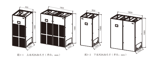
The structural dimensions of the indoor unit are shown in Figures 3-1 and 3-2.

Air-cooled Outdoor Unit
The structural dimensions of the outdoor unit are shown in Figures 3-3 and 3-4.

Table 3-1 SW Series Condenser Mechanical Parameters (Unit: mm)
Product Model | Overall Dimensions | |||
L | H | W | H1 | |
SW40NP | 1650 | 1150 | 1100 | 710 |
SW50NP | 1650 | 1150 | 1100 | 710 |
SW70NP | 2010 | 1150 | 1100 | 710 |
SW80NP | 2860 | 1150 | 1100 | 710 |
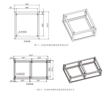
The shape and dimensions of the indoor unit (bottom supply air) installation base are shown in Figures 3-5, 3-6, and Table 3-2.

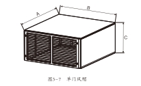
For top air discharge systems, an air supply hood with a grille can be selected as required. The shape of the air hood is shown in Figure 3-7, and specific dimensions refer to Table 3-3.

Type | A | B | C |
Single Door | 1000 | 900 | 450 |
Double Door | 1000 | 1800 | 450 |

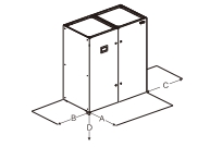
Space Location | Down-blowing | Top Supply Air |
A | 900 | 900 |
B | 600 | 600 |
C | 600 | 600 |
D | 500 | 0 |
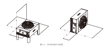
Outdoor unit maintenance space, as shown in Figure 3-9.

Space Location | Front Placement | Side Placement |
A | 600 | 600 |
B | 4000 | 4000 |
C | 600 | 600 |
D | 600 | / |
VIII. Refrigerant Piping
General Principles
Air-cooled systems require the connection of refrigerant piping between the indoor and outdoor units. Typically, installers need to confirm the equivalent length of the refrigerant piping based on site conditions to determine the connection method. The equivalent length of the piping should consider the resistance caused by various fittings. Please refer to the following principles: 1. If the single-pass equivalent length exceeds 30m, or the vertical height difference between the indoor and outdoor units exceeds 7.5m, please consult the manufacturer before installation to confirm whether pipe extension components or other measures are required.
2. The recommended pipe dimensions in Table 4-2 are equivalent lengths, with resistance losses from elbows and valves already calculated. Installers should confirm suitability based on site conditions.
3. When there is a significant height difference between the indoor and outdoor units, install an oil trap (oil reservoir) every 7.5m. Overly long connecting pipes require sufficient compressor oil replenishment. For details, please consult the manufacturer before installation.
Liquid Pipe Outer Diameter | Equivalent Dimensions | ||
45° Elbow | 90° Elbow | 180° Elbow | |
16 | 0.15 | 0.27 | 0.54 |
19 | 0.18 | 0.30 | 0.60 |
22 | 0.24 | 0.44 | 0.88 |
28 | 0.30 | 0.56 | 1.12 |
Piping Layout
During installation, piping can be laid out by referring to Figures 4-1 and 4-2.
IX. Refrigerant Piping
Piping
Indoor and outdoor units are connected by welding. Before welding, wrap the ball valve with a cloth and pour water over it to ensure the ball valve temperature does not exceed 120°C. There are many warning and instruction labels and moisture-proof cotton on the bottom plate and side plates of the air conditioner near the ball valve. Do not burn the labels and insulation cotton during welding. The horizontal part of the exhaust pipe should be inclined downwards after being led out from the compressor, with a slope of at least 1:200 (5mm drop per 1m). The exhaust pipe should be insulated if it is affected by cooling equipment (including under the floor). Considering the influence of pipe diameter on system pressure drop, please select the diameter of the connecting copper pipe of indoor and outdoor units according to the construction dimensions in Table 4-3 as much as possible.
General Principles
Indoor units can be divided into top-blowing and bottom-blowing according to the air outlet method. For the connection of the air-cooled system, air ducts can be connected or air hoods can be selected (for top-blowing). Comprehensive consideration is needed when connecting air ducts.
Please refer to the following principles when installing air ducts:
The ratio of the long side to the short side of the rectangular air duct should not be greater than 4:1.
For bending rectangular air ducts, inner arc or inner oblique rectangular bends can be used. When the side length is greater than or equal to 500mm, flow guides should be set.
When the side length of the rectangular air duct is greater than or equal to 630mm, the insulated air duct side length is greater than or equal to 800mm, and the pipe section length is greater than 1200mm, additional support should be adopted.
The surface of the air duct and accessories should be smooth, the arc should be uniform, the bite seam should be tight, and the detachable interface and adjusting mechanism of the air duct and accessories should not be installed on the top or in the floor.
The airtightness test of the air duct should meet the leakage light test standard.
Piping Layout
Pay special attention when connecting air ducts: When multiple air conditioning units share the same static pressure box, the mutual interference of airflows from the air conditioning units should be avoided or reduced as much as possible.
Bottom-blowing units are recommended for free return air and are not recommended for return air ducts. If a return air duct must be installed, please install a static pressure box above the unit, and the height of the static pressure box should not be less than 600mm. Do not use "odd heads" or "reduced mouths" to replace the static pressure box, otherwise it will cause the unit to alarm.

X. Electrical and Control
Main Circuit Connection
Power requirements for the newly launched DX series air conditioners:
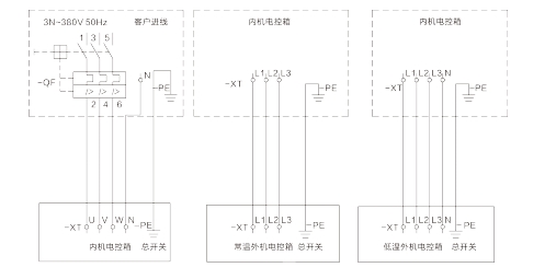
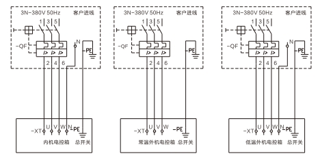
Indoor unit uses 3N+PE-380, 50Hz; outdoor unit uses 3+PE-380, 50Hz. Refer to the nameplate of the air conditioning unit for the specific current. The wire diameter should be determined by considering the full-load current and the influence of the working environment. All electrical wiring should comply with local standards, and check that the power supply is consistent with the nameplate requirements. To avoid corrosion and overheating at the terminal connections, all power supply wires must be copper wires. The power connection diagram is shown in Figure 4-4:
Customer Power Connection (Single-phase power supply for indoor unit, outdoor unit powered by indoor unit)

Customer Power Connection (Outdoor unit with separate power supply)

XI. Application Guide
Controller Connection
The new standard DX series air conditioners provide a dedicated terminal block, mainly providing external interfaces for remote control, alarm monitoring, etc. Users can connect the following monitoring and alarm devices:
1. Remote shutdown. The unit is equipped with a passive signal interface for remote shutdown. This signal should be disconnected normally. To remotely shut down, please close this passive signal. When the remote shutdown signal is closed, the unit will shut down and generate a remote shutdown alarm. Refer to the electrical schematic diagram and installation instructions included in the package for connection.
2. Smoke alarm. The unit is equipped with a passive signal interface for smoke alarm. This signal should be disconnected normally. When the smoke alarm signal is closed, the unit will shut down and generate a smoke alarm. Refer to the electrical schematic diagram and installation instructions included in the package for connection.
3. Blue control system. The unit is equipped with an RS485 interface and supports MODBUS-RTU protocol.
4. Alarm signal output. When the unit encounters any alarm, the unit alarm output signal is closed; otherwise, it is open. The unit alarm output signal is a passive contact signal.
Refer to the electrical schematic diagram and installation instructions included in the package for connection.
Multi-unit group control: Multiple units can be linked for group control and main/backup rotation. Multi-unit linkage is achieved through CAN bus, with a maximum of 32 units. Unit 1 (address 0) is the default master control unit, and other units are set to addresses 1-31 respectively. If the master control unit fails to communicate or the network fails, each unit will operate independently. The master control unit sends control commands to each unit and obtains measurement data and unit status from the slave units. Multi-unit group control can achieve the following functions:
1. Module 1: The host compares the average controlled humidity value of all operating units with the host's controlled humidity set value to calculate the direction of the room humidity demand. The units in the group control network operate according to the direction of the room humidity demand. Standby, time rotation, fault rotation, and cascading functions are allowed.
2. Module 2: The units in the group control network compare their own detected controlled humidity value with the host's controlled humidity set value to determine the output direction and intensity. Standby, time rotation, fault rotation, and cascading functions are allowed.
I. Product Introduction

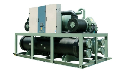
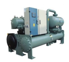
The new Ya DST series screw air conditioning units are divided into four series: screw-type water-cooled chillers, screw-type water-source heat pump units, screw-type air-cooled chillers, and screw-type air-cooled heat pump units.
II. Product Features
High Efficiency and Energy Saving
With the production capacity of major components and independent intellectual property rights, the system is perfectly matched, and the overall efficiency reaches 6.0. The unit can be optionally equipped with the company's independently patented heat recovery device, which can recover more than 30% of the cooling capacity under air conditioning conditions or achieve full heat recovery. The maximum hot water temperature can reach 70°C. Heat recovery does not consume electricity, and the overall efficiency of the unit can be increased by 5%.
Reliable Operation
The unit has seven safety protection measures to ensure normal operation. The unit is available in single and dual-circuit designs to meet different customer needs. When a single compressor in a dual-circuit unit fails, the other compressor can still operate normally, minimizing the impact of the failure. All units undergo 100% safety testing before leaving the factory to ensure that the unit's performance meets company standards.
Intelligent Control
The unit uses microcomputer control and can be operated through a centralized management system. The unit can be optionally equipped with a remote management program to feedback system operation information and enable remote service. The control interface directly displays the fault content, facilitating timely understanding and troubleshooting of faults.
Easy Installation and Maintenance
The unit is pre-charged with refrigerant and lubricating oil at the factory. Customers only need to connect the water inlet and outlet pipes and the power supply to operate.
Standard Configuration | |
Compressor | Semi-hermetic twin-screw compressor |
Evaporator | Self-produced high-efficiency evaporator |
Condenser | Self-produced high-efficiency condenser |
Controller | Microcomputer controller |
Expansion device | Microcomputer controller |
Start-up method | Star-delta |
Power System | 380V-50HZ--3N |
Insulation material | Corrosion-resistant, waterproof, mesh insulation layer |
Packaging | High-strength plastic cloth |
Paint | High-strength matte paint |
Water port connection method | Flange |
The screw-type water-cooled chiller uses a high-efficiency twin-screw compressor, matched with a high-efficiency condenser and evaporator produced by our factory, and a brand expansion valve. Application range of the unit: various air-conditioning and heating in large, medium, and small commercial places. Cooling capacity range: 70KW-5000KW.

A variety of refrigerants are available. The unit can provide refrigerants such as R22 and R134a. The chilled water outlet temperature range is 5-20 degrees. 380V-50HZ-3N and other power systems are available. Modular design allows for flexible combinations.
Standard Configuration | |
Compressor | Heat pump dedicated compressor |
Evaporator | Self-produced high-efficiency evaporator |
Condenser | Self-produced high-efficiency condenser |
Controller | Microcomputer controller |
Expansion device | Microcomputer controller |
Start-up method | Star-delta |
Power System | 380V-50HZ--3N |
Insulation material | Corrosion-resistant, waterproof, mesh insulation layer |
Packaging | High-strength plastic cloth |
Paint | High-strength matte paint |
Water port connection method | Flange |
The screw-type water-source heat pump unit uses a twin-screw compressor. The water-source heat pump system can provide heating and cooling, making it versatile. One system can replace the original boiler and air conditioning systems, saving a significant amount of energy and reducing initial equipment investment.
Product Inquiry
*Note: Please fill in the information accurately and keep the communication open. We will contact you as soon as possible.