
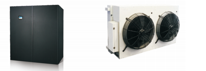
DX直膨式房间级精密空调机组
Product Category:
Keywords:
| 1 | 2 | 3 | 4 | 5 | 6 | 7 | 8 | 9 | 10 |
| HM | 070 | A | X | P | E | K | B | M | 0 |
| 1 | 2 | 3 | 4 | 5 | 6 |
| SW | 50 | N | P | H | M |
注:如产品有上表无法体现的特殊技术和功能要求 , 请联系新雅空调确认产品型号。
| 序号 | 类别 | 代码 | 描述 |
| 1 | 系列名称 | SW | 机房专用空调室外机 |
| 2 | 换热量 | 50 | 换热量级别 |
| 3 | 压缩机位置 | N | 压缩机放室内 |
| 4 | 换热器名称 | P | 平板式 |
| V | V型集中式 | ||
| 5 | 制冷剂 | H | 制冷剂R410A (标配) |
| 6 | 电源制式 | M | 3 + PE ~ 380V , 50HZ (标配) |
| Q | 3+ PE ~ 380V , 60Hz | ||
| 一 | 其他 |
室内机型号说明
| 序号 | 类别 | 代码 | 描述 |
| 1 | 系列名称 | HM | 新雅DX系列房机专用空调 |
| 2 | 制冷量 | 070 | 制冷量级别 |
| 3 | 冷却方式 | A | 风冷 |
| W | 水冷 | ||
| 一 | 其他 | ||
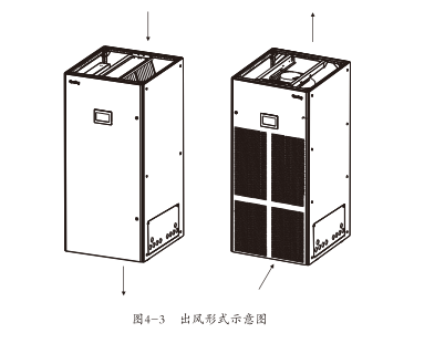
| 4 | 送风方式 | X | 风,风机下沉式送风 |
| D | 下送风 | ||
| U | 上送风(可配风帽实现前送风) | ||
| 5 | 功能 | B | 制冷功能 |
| R | 制冷、加热功能 | ||
| H | 制冷、加温功能 | ||
| P | 制冷、加热、加湿功能 | ||
| 风机型式 | E | EC风机 | |
| 7 | 系统配置 | J | R410A单系统(单系统标配,25~45kW) |
| K | R410A双系统(双系统标配,50~90kW) | ||
| 一 | 其他 | ||
| 8 | 出管方式 | L | 左出管(标配,除双系统机组外) |
| R | 右出管 | ||
| B | 左模块左出管,右模块右出管(标配,双系统机组) | ||
| 9 | 电源制式 | M | 3N+PE~380V,50Hz(标配) |
| Q | 3N+PE-380,60Hz | ||
| 一 | 其他 | ||
| 10 | 特殊功能 | 0 | 无(标配) |
| 1 | 配冷凝水泵 | ||
| 一 | 其他 |
注:如产品有上表无法体现的特殊技术和功能要求 , 请联系新雅空调确认产品型号。
| 形式多样化 按送风方式可分为上送风和下送风等形式多样化的形式满足不同的安装和使用环境的要求。 制冷量范围广 制冷量25kW~110kW,可以自由选配以适用大、中、小各类机房 控制精确 显度精度可控制在土1C,湿度精度可控制在土5%RH。 能效高 采用高效涡旋压缩机、高效V/IA型翅片式换热器、精细设计的分液头以及更加合理的内部布局,使得空调内部空气流场更加 匀,冷媒分配更加合理,从而极大地提高了换热器的换热效率,使空调机组达到高效节能的效果。 方便耐用 独特的模块化框架,结构紧凑,整体尺寸小,既稳定坚固又容易拆分,可满足极限条件下搬运的要 求:采用保温棉,机身内的 保温性能良好:单门、双门结构件通用性较高,大大减少了易损件(如空气过滤器等)的规格。 红外加湿 采用先进的红外加湿技术,有效地减少了加湿器对水质的依赖性湿度控制快速、准确。 环保冷媒 适应国际上对环保冷媒的要求采用R410A环保制冷剂。 多重保护 完善的诊断和自动报警功能,能更有效地防止故障发生及更快速地寻找故障位置, 全方位地保护 机组有效地延长了空调机组的使用寿命。 便于维护 整机采用完全的前开门,所有部件的维护都可在正面进行,节省了使用空间。 |

|
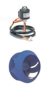
| 室内机 室内机主要由压缩机、蒸发器、膨胀阀、风机、视液镜、干燥过滤器、红外加湿器、 PTC加热器、安全控制装置、空气过滤器等部件组成。 压缩机 压缩机采用了高效涡旋压缩机(如图1-3),具有震动小、噪音低及可靠性高等特点。 蒸发器 采用高效VIA型翅片式蒸发器(如图1-4)。翅片为亲水开槽片,内螺纹铜管,换热效率更 高。针对具体机型进行设计和验证适当的分配器保证冷媒在每个回路分配的均匀性极 大地提高了换热器的效率。 |

|
| 室外机 | |
| 节流装置 配置高精度电子膨胀阀控制(如图1-5),在线专家式算法精确控制制冷剂流量,运行 更加节能,系统更加安全、稳定。 |
|
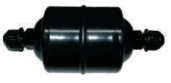
| 干燥过滤器 干燥过滤器(如图1-7)在--段时间内能有效除去制冷系统中存在的水分,同时过滤系 统中长期运行产生的杂质,保证系统正常运行。 |
|
| 风机 采用无蜗壳离心风机(如图1-6),具有风量大,送风距离远,维护方便可靠性高、无 极调速等特点。先进的风机故障反馈系统,可以自动判断由于风机运转异常造成的 机组风量减少,并且停止正在运行的加热或加湿等工作,同时发出报警信号。 |
|
| 红外加湿器 红外加湿器(如图1-8)微处理器控制。结构简清:易于拆卸:清洗和维护。悬挂在不锈 钢加湿水盘上的高强度石英灯管发射出红外光和远红外光,在5~6秒内,使水盘中 的水分子吸收辐射能以摆脱水的表面张力,在纯净状态下蒸发,不含任何杂质。红外 加湿器的应用减少了系统对水质的依赖性,其自动冲洗功能,使水盘更清洁。 |
|
| 视液镜 系统循环的窗口,可观察冷媒状态,同时检测系统水份含量。当系统含水量超标时,其 底色变为告警区域颜色。 |
|
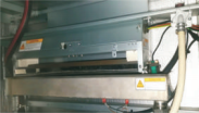
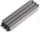
| PTC电加热 采用PTC电加热(如图1-9),具有安全、节能、制热迅速及使用环境温度范围和电压 范围宽等优点。其发热量既能维持机房的干球温度同时又可以补偿除湿时造成的温 度下降,PTC加热器较低的表面温度可以防止空气产生电离,从而延长了使用寿命。 |
|
| 安全控制装置 每个制冷系统都装有高、低压保护和排气温度保护装置。当压缩机的排气压力或排 气温度过高时发出紧急报警并进行保护;当压缩机因吸气压力过低无法正常工作 时,发出报警信号,并进行保护。每个风机都装有热过载保护继电器,当风机出现过载 时能够及时进行保护。滤网脏堵开关,可对空调机组的风系统进行实时监控。 |
|
| 空气过滤器 采用标准空气过滤器(如图1-10),方便更换。过滤效率等级为G4(EN779),平均过 滤效率达90%以上从而有效的保证证机房的洁净度。 |
|
| 室外机 节流装置 配置高精度电子膨胀阀控制(如图1-5),在线专家式算法精确控制制冷剂流量,运行更加节能,系统更加安全、稳定。 干燥过滤器 干燥过滤器(如图1-7)在--段时间内能有效除去制冷系统中存在的水分,同时过滤系统中长期运行产生的杂质,保证系统正常运行。 风机 采用无蜗壳离心风机(如图1-6),具有风量大,送风距离远,维护方便可靠性高、无极调速等特点。先进的风机故障反馈系统,可以自动判断由于风机运转异常造成的机组风量减少,并且停止正在运行的加热或加湿等工作,同时发出报警信号。 红外加湿器 红外加湿器(如图1-8)微处理器控制。结构简清:易于拆卸:清洗和维护。悬挂在不锈钢加湿水盘上的高强度石英灯管发射出红外光和远红外光,在5~6秒内,使水盘中的水分子吸收辐射能以摆脱水的表面张力,在纯净状态下蒸发,不含任何杂质。红外加湿器的应用减少了系统对水质的依赖性,其自动冲洗功能,使水盘更清洁。 PTC电加热 采用PTC电加热(如图1-9),具有安全、节能、制热迅速及使用环境温度范围和电压范围宽等优点。其发热量既能维持机房的干球温度同时又可以补偿除湿时造成的温度下降,PTC加热器较低的表面温度可以防止空气产生电离,从而延长了使用寿命。 安全控制装置 每个制冷系统都装有高、低压保护和排气温度保护装置。当压缩机的排气压力或排气温度过高时发出紧急报警并进行保护;当压缩机因吸气压力过低无法正常工作时,发出报警信号,并进行保护。每个风机都装有热过载保护继电器,当风机出现过载时能够及时进行保护。滤网脏堵开关,可对空调机组的风系统进行实时监控。 风冷室外机 标准型 采用波纹型翅片管换热器具有高散热效率清洗、维护方便等特点:外转子轴流式风机,独特的“镰刀”形金属扇叶,具有优越的空气动力特性效率高;六极和八极风机,配合专门设计的导风圈,使得流经叶片的气流噪声显著降低钎对基站电网环境定制的高性能三相电机,适用电压范围广,可靠性高先进的风机转速控制系统通过检测系统的冷凝压力调整输出电压,从而控制室外风机转速,使系统压力与热负荷相适应,有效降低风机噪 声,保证系统的稳定、可靠、高效运行;采用变频调速室外风机,最大支持可调节范围10%~100%,适用不同温度环境的配置。节能型(选配)在标准型基础上。通过独特设计提高整个系统的能效比。使整机更加节能更加高效,同时可满足+45x55℃的高温环境。 节能型(选配) 在标准型基础上增加低温组件和电控箱防冻保护,使整个系统最低可在-40℃下正常运行。微处理控制器是为了让机组满足机房特殊要求而设计的,具有稳定性好、控制精度高、智能化等优点。室内机前门提供真彩触摸显示屏(LED)操作面板。简单易懂的操作界面显示室内当前的温度、湿度、温湿度设定值、设备(风机、压缩机、制冷、制热、除湿、加湿等)输出百分比及报警情况。用户可以从显示屏的主菜单进入浏览 或设置各设定点、事件记录、图形数据、传感器数据、报警设置等信息。液晶显示屏背光采用节能设计,当超过定时间(出厂值为5min,可通过菜单配置)无任何按键操作时,背光熄灭;再次发生按键操作时,背光点亮。控制系统还支持多机群控,智能地实现扩容,多个预留接口可以实现多种 监控方式。微处理控制器面板如图1-11所示。 控制系统 用户界面操作简洁,多级密码保护,有效防止非法操作。控制器具有掉电自恢复和高、低电压保护功能。 通过菜单操作可以准确了解各主要部件运行时间。专家级故障诊断系统自动显示当前故障内容,方便维护人员进行设备维护。 可存储400条历史事件记录记录消息、警告、报警三种事件。 配置RS485接口,通信协议采用标准通信协议。 温度设定。温度设定范围为18°C-32°C 湿度设定湿度设定范围为40%RH~95%RH。 报警信号. 微处理器具有声、光信号报警功能标准报警信息如下: 高温报警、低温报警、高湿报警、低湿报警、系统高压报警、系统低压报警、滤网脏堵报警其他用户自定义 报警背光点亮。控制系统还支持多机群控智能地实现扩容多个预留接口可以实现多种监控方式。 微处理控制器面板如图1-11所示。 |

图1-11控制器面板 |
| 选配部件 上送风风格 对于上送风系统可选配套的带送风格栅风棍保证出风的均匀性。 延长组件 对长连接管的使用场合,可采用延长组件。在压缩机停机后延长组件能有效地防止冷媒倒流和集中,保证压缩机的下一次正常启动使系统更加安全可靠。 漏水报警绳式、单点式漏水探测器可向机组或一一个独立的监控系统提供报警信号,触发机组报警,及时关闭机组以便及时处理。 烟感探测器 烟感探测器探测到烟雾时,可立即触发报警系统从而关闭机组。 火灾探测器 火灾探测器监控现场的回风温度-旦遇到高温便立即关闭机组。 高效空气过滤器 高效空气过滤器适用于洁净度要求更高的使用环境。 湿膜加湿器 湿膜加湿器(如图1-12)是空调内置加湿器件,构造简洁,洁净无噪音,采用有机湿膜环保材料,吸水性优良,饱和效率高材质轻,易生产体积小,节省空间,便于拆装、清洗和维护。同时对空气有洗涤、过滤作用,可实现洁净、等焓加湿功能。加湿运行时,湿膜本体无功耗节能显著。注:单冷机型不带加热加湿。 |
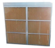
图1-12湿膜加湿器 |
四、冷风/水冷机组技术参数
表2-1风冷机组技术参数
| 室内机型号 | HM025A | HM030A | HM035A | HM040A | HM045A | HM050A |
| 主电源 | 3N+PE~380V50Hz | |||||
| 室内回风工况:24℃ DB/17℃ WB;室外环境工况:(风冷)35℃ | ||||||
| 制冷 制冷量-kW | 26.4 | 31.5 | 36.1 | 38.1 | 45.7 | 52.7 |
| 系统 显冷量-kW | 24.5 | 29.2 | 33.4 | 35.2 | 41.6 | 48.9 |
| 压缩机 | ||||||
| 台数(个) | 1 | 1 | 1 | 1 | 1 | 2 |
| 室内风机 | ||||||
| 风机 循环风量-m³/h | 7500 | 9000 | 10500 | 11500 | 12000 | 15000 |
| 参数 台数(个) | 1 | 1 | 1 | 1 | 1 | 2 |
| 电加热性能参数 | ||||||
| 加热能力-kW | 6 | 6 | 6 | 6 | 6 | 9 |
| 加湿器性能参数 | ||||||
| 加湿能力-kg/h | 4.5 | 4.5 | 4.5 | 4.5 | 4.5 | 6.5 |
| 过滤网 | ||||||
| 过滤等级 | G4 | |||||
| 连接管尺寸规格 | ||||||
| 液体管-mm(焊接) | 15.88 | 15.88 | 15.88 | 15.88 | 15.88 | 15.88 |
| 气体管-mm(焊接) | 22 | 22 | 22 | 22 | 22 | 22 |
| 加湿器进水管(内螺纹) | G1/2" | G1/2" | G1/2" | G1/2" | G1/2" | G1/2" |
| 排水管OD-mm(宝塔+喉箍) | 19 | 19 | 19 | 19 | 19 | 19 |
| 室内机满负载电流及功率(带加热加湿机型) | ||||||
| 室内机满负载电流-A | 32.12 | 38.2 | 41.05 | 41.05 | 48.97 | 59.74 |
| 室内机满负载功率-KW | 19.07 | 22.71 | 23.93 | 23.93 | 28.28 | 35.14 |
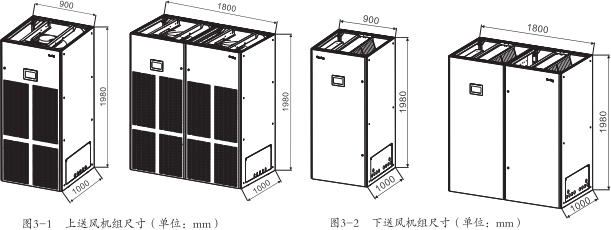
| 室内机机组尺寸 | ||||||
| 机组宽度-mm | 900 | 900 | 900 | 900 | 900 | 1800 |
| 机组深度-mm | 1000 | 1000 | 1000 | 1000 | 1000 | 1000 |
| 机组高度-mm | 1980 | 1980 | 1980 | 1980 | 1980 | 1980 |
| 室内机机组重量 | ||||||
| 室内机机组静重-kg | 355 | 370 | 375 | 380 | 390 | 665 |
| 室外机型号 | 1*SW40NP | 1*SW50NP | 1*SW50NP | 1*SW50NP | 1*SW70NP | 2*SW40NP |
| 主电源 | 380V 3Ph 50Hz | |||||
| 室外机满负载电流及功率(室内机与室外机分开配电) | ||||||
| 室外机满负载电流-A | 2.9 | 4.7 | 4.7 | 4.7 | 5.8 | 2*2.9 |
| 室外机满负载功率-KW | 1.06 | 1.8 | 1.8 | 1.8 | 2.1 | 2*1.06 |
| 室外机尺寸 | ||||||
| 机组宽度-mm | 1650 | 1650 | 1650 | 1650 | 2010 | 1650 |
| 机组深度-mm | 1100 | 1100 | 1100 | 1100 | 1100 | 1100 |
| 机组高度-mm | 1150 | 1150 | 1150 | 1150 | 1150 | 1150 |
| 室外机机组重量 | 158 | 168 | 168 | 168 | 210 | 2*158 |
| 室内机型号 | HM060A | HM070A | HM080A | HM090A | HM100A | HM110A | |
| 主电源 | 3N+PE~380V 50Hz | ||||||
| 室内回风工况:24℃DB/17℃WB;室外环境工况:(风冷)35℃ | |||||||
| 制冷系统 | 制冷量-kW 显冷量-kW |
62.9 | 72.3 | 76.1 | 91.6 | 100.2 | 112.8 |
| 58.2 | 66.6 | 70.2 | 83.4 | 91.6 | 105.2 | ||
| 压缩机 | |||||||
| 台数(个) | 2 | 2 | 2 | 2 | 2 | 2 | |
| 室内风机 | |||||||
| 循环风量-m³/h 风机参数 台数(个) |
18000 | 21000 | 23000 | 24000 | 25600 | 28000 | |
| 2 | 2 | 2 | 2 | 2 | 2 | ||
| 电加热性能参数 | |||||||
| 加热能力-kW | 9 | 9 | 9 | 9 | 9 | 9 | |
| 加湿器性能参数 | |||||||
| 加湿能力-kg/h | 6.5 | 6.5 | 6.5 | 6.5 | 6.5 | 6.5 | |
| 过滤网 | |||||||
| 过滤等级 | G4 | ||||||
| 连接管尺寸规格 | |||||||
| 液体管-mm(焊接) | 15.88 | 15.88 | 15.88 | 15.88 | 15.88 | 15.88 | |
| 气体管-mm(焊接) | 22 | 22 | 22 | 22 | 22 | 22 | |
| 加湿器进水管(内螺纹) | G1/2" | G1/2" | G1/2" | G1/2" | G1/2" | G1/2" | |
| 排水管OD-mm(宝塔+喉箍) | 19 | 19 | 19 | 19 | 19 | 19 | |
| 室内机满负载电流及功率(带加热加湿机型) | |||||||
| 室内机满负载电流-A | 71.92 | 77.6 | 77.6 | 93.44 | 93.44 | 104.34 | |
| 室内机满负载功率-KW | 42.54 | 44.86 | 44.86 | 53.56 | 53.56 | 57.60 | |
| 室内机机组尺寸 | |||||||
| 机组宽度-mm | 1800 | 1800 | 1800 | 1800 | 1800 | 1800 | |
| 机组深度-mm | 1000 | 1000 | 1000 | 1000 | 1000 | 1000 | |
| 机组高度-mm | 1980 | 1980 | 1980 | 1980 | 1980 | 1980 | |
| 室内机机组重量 | |||||||
| 室内机机组静重-kg | 695 | 705 | 715 | 735 | 755 | 800 | |
| 室外机型号 | 2*SW50NP | 2*SW50NP | 2*SW50NP | 2*SW70NP | 2*SW70NP | 2*SW80NP | |
| 主电源 | 380V 3Ph 50Hz | ||||||
| 室外机满负载电流及功率(室内机与室外机分开配电) | |||||||
| 室外机满负载电流-A | 2*4.7 | 2*4.7 | 2*4.7 | 2*5.8 | 2*5.8 | 2*5.8 | |
| 室外机满负载功率-KW | 2*1.8 | 2*1.8 | 2*1.8 | 2*2.1 | 2*2.1 | 2*2.1 | |
| 室外机尺寸 | |||||||
| 机组宽度-mm | 1650 | 1650 | 1650 | 2010 | 2010 | 2860 | |
| 机组深度-mm | 1100 | 1100 | 1100 | 1100 | 1100 | 1100 | |
| 机组高度-mm | 1150 | 1150 | 1150 | 1150 | 1150 | 1150 | |
| 室外机机组重量 | |||||||
| 室外机机组静重-kg | 2*168 | 2*168 | 2*168 | 2*210 | 2*210 | 2*256 | |
| 项目 | 条件 |
| 环境温度 | 室内:0℃~40℃ |
| 室外:标准型: -20℃~+45℃ | |
| 节能型:-20℃~+55℃ | |
| 低温型: -40℃~+45℃ | |
| 室内环境湿度 | 20%~80%RH |
| 防护等级(室外机) | IPX4 |
| 海拔 | ≤1000m |
| 电源适应性 | 380V±15%,50±1Hz |
注 :
在以下情况下使用时;请向申新雅空调专业技术人员咨询:
1、空调机组电压超出额定电压的10%或低于90%,机外余
压超过200Pa。
3、海拔超过1000m 时,需要降额使用。
冷风室外机
室外机的结构尺寸如图3 - 3和图3 - 4所示。
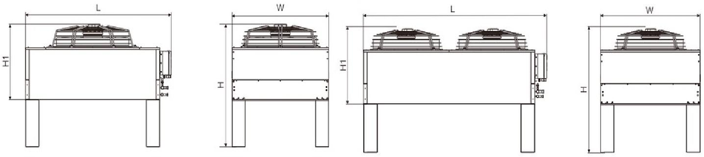
表3-1 SW系列冷凝器机械参数(单位:mm)
| 产品型号 | 外形尺寸 | |||
| L | H | W | H1 | |
| SW40NP | 1650 | 1150 | 1100 | 710 |
| SW50NP | 1650 | 1150 | 1100 | 710 |
| SW70NP | 2010 | 1150 | 1100 | 710 |
| SW80NP | 2860 | 1150 | 1100 | 710 |
室内机(下送风)安装底座外形及其尺寸如图3-5、3-6和表3-2所示。
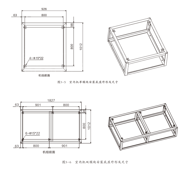
表3-2安装底座高度尺寸
| 产品型号 | 外形尺寸 |
| 安装底座高度 | H≥500mm(下出风机组,根据地板高度决定) |
注:安装底座要根据实际的底板固定孔的位置进行开孔,孔径为φ15mm。
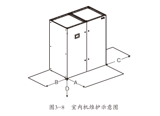
六 、风帽尺寸
对 于 上 出 风 系 统 , 可 以 根 据 要 求 选 择 带 有 格 栅 的 送 风 风 帽 , 风 帽 的 外 形 如 图 3 - 7 , 具 体 尺 寸 参 见 表 3 - 3 。
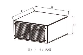
表 3 - 3 风 帽 尺 寸 ( 单 位 :mm)
| 类型 | A | B | C |
| 单门 | 1000 | 900 | 450 |
| 双门 | 1000 | 1800 | 450 |
注:若空调机组选配高度超过450mm 的风帽,需联系厂家进行非标制作。
最 小 的 维 护 空 间 要 求 如 表 3 - 4 所 示
表 3 - 4 最 小 的 维 护 空 间 数 ( 单 位 :mm)
| 空间位置 | 下送风 | 上送风 |
| A | 900 | 900 |
| B | 600 | 600 |
| C | 600 | 600 |
| D | 500 | 0 |
室 外 机 维 修 空 间 , 如 图 3 - 9 所 示 。
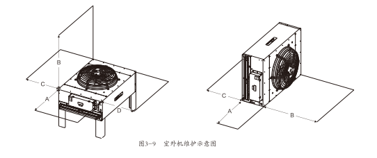
表3-5最小维护空间(单位:mm)
| 空间位置 | 正放 | 侧放 |
| A | 600 | 600 |
| B | 4000 | 4000 |
| C | 600 | 600 |
| D | 600 | / |
注:这些空间用来提供给日常维护。
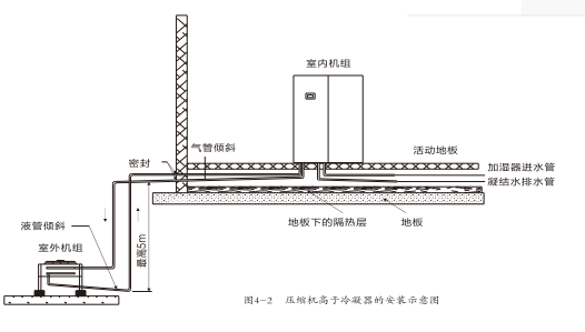
1、 若单程等效长度超过30m, 或是室内机与室外机的垂直高度差超过了7 .5m, 在安装前请向厂家咨询以确认是否需要增加管路延长组件等措施。
2、 表4-2建议的管路尺寸为等效长度,弯头以及阀门带来的阻力损失已计算在内。安装者要根据现场情况确认是否合适。
3. 在室内机和室外机的高度落差较大时,每隔7 .5m 安 装 一个集油器(存油弯),过长的连接管需要补充足够的压缩机油,具体可在安装前向厂家咨询。 维
| 液管外径 | 等效尺寸 | ||
| 45°弯头 | 90°弯头 | 180°弯头 | |
| 16 | 0.15 | 0.27 | 0.54 |
| 19 | 0.18 | 0.30 | 0.60 |
| 22 | 0.24 | 0.44 | 0.88 |
| 28 | 0.30 | 0.56 | 1.12 |
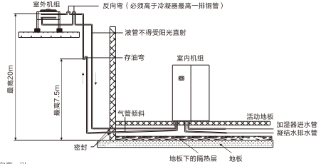
注:冷凝器高于压缩机时,在冷凝器进气管和出液管上需加装反向弯,以避免停机时液体回流。安装反向弯时,必须保证反向弯顶端弯管高于冷凝器最高一排铜管。
九、制冷剂管路
接 管
室内外机通过焊接方式连接,焊接前注意在球阀上包上湿布并淋水,保证球阀温度不超过120℃。在球阀附近的空调机组底板和侧板上贴有较多的注意和指引标签及保温棉,焊接时不要烧掉标签和保温棉。排气管的水平部分应从压缩机引出后向下倾斜,其倾斜度至少为1:200(每1m 应下降5mm) 。排气管若是在受冷却设备影响的地方(包括垫高的地板下)时应该保温。考虑到管径对系统压降的影响,室内外机的连接铜管的管径,请尽量按照表4-3的建议尺寸选取。
表4 - 3管路建议参考尺寸
| 型号 | HM025A HM050A |
HM030A HM035A HM060A HM070A |
HM040A HM080A |
HM045A HM090A |
HM100A HM110A |
||
| 管长 | D L | D L | D L | D L | D | ||
| 10m 20m 30m 40m* 50m* 60m* |
22 | 16 | 22 16 28 |
22 16 28 19 |
22 16 28 19 |
22 28 28 |
16 19 |
一般原则
室内机按出风方式可分成上出风和下出风,对于风冷系统的连接,可以接风管也可以选配风帽(针对上出风),在接风管的
时候需要综合考虑。
安装风管时请参考以下原则:
●矩形风管的长边与短边之比不宜大于4:1。
●矩形风管的弯管,可采用内弧形或内斜线矩形弯管。当边长大于或等于500mm时,应设置导流片。
●当矩形风管边长大于或等于630mm,保温风管边长大于或等于800mm,且其管段长度大于1200mm时,均应采取加固
措施。
●风管与配件的表面应平整,圆弧应均匀,咬口缝应严密。而且风管与配件可拆卸的接口及调节机构,不得装设在墙上
或楼板内。
·风管的严密性检验应符合漏光法检测规范。
布管
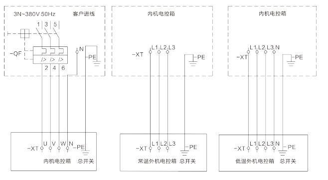
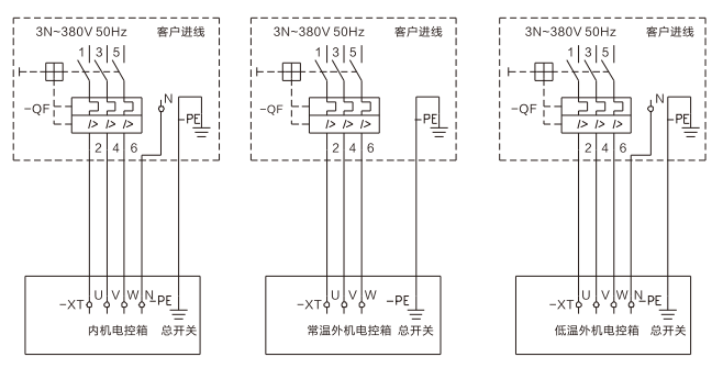
客户电源接线(室外机单独供电)
制器链接
新雅DX系列空调提供了专门的端子排,主要为用户提供远程控制、报警监控等外部接口。
用户可以接入以下监控和报警装置:
1、远程关机。机组预留远程关机无源信号接口,要求正常时该信号断开,需要远程关机时请把该无源信号变成闭合,当远程关机信号闭合后,机组会关闭并产生远程机报警,连接时参考随机附带的电气原理图和安装说明书。
2、烟雾告警。机组预留烟雾告警无源信号接口,要求正常时该信号断开。当烟雾告警信号闭合后,机组会关闭并产生烟雾告警,连接时参考随机附带的电气原理图和安装说明书。
3、监控系统。机组预留RS485接口,支持MODBUS-RTU协议。
4、报警信号输出。当机组发生任一报警时,机组报警输出信号闭合,否则断开。机组报警输出信号为一个无源触点信号,连接时参考随机附带的电气原理图和安装说明书。
多机群控
多台机组可以进行联控,从而实现群组控制和主备轮巡的功能。多机联控通过CAN总线实现,最多可连接32台,1号机组:(地址为0)默认为主控机组,其它机组分别设置地址为1-31,如果主控机组通讯、组网失败,各机组单独运行。主控机组向海台机组发送控制命令,并从从机读取测量数据和机组状态。
多机群控可以实现以下功能:
1、模块一主机根据所有运行机组的平均被控温湿度值与主机被控温湿度设定值进行比较计算出机房温湿度需求方向,群控网络中的机组按照机房温湿度需求方向运行工作。允许备用、时间轮值、故障轮值、层叠功能。
2、模块二:群控网络中的机组根据自身检测的被控温湿度值与主机被控温湿度设定值进行比较,确定输出方向和输出力度。允许备用、时间轮值、故障轮值、层叠功能。


Product Inquiry
*Note: Please fill in the information accurately and keep the communication open. We will contact you as soon as possible.
Online Message
Thank you for your valuable opinions and suggestions. We will reply to you as soon as possible!
New Super-Aire Equipment Ltd.
Address: Laocun Industrial Zone, Sanle Road, Lecong Town, Shunde District, Foshan City, Guangdong Province
Tel: 0757-28850303 / 0757-28850330
Tel: 0757-28862319 / 0757-28831625
Fax: 0757-2886 9823
Email: xykt@xykt.com.cn

Follow Douyin account

Mobile version


Copyright © 2025 New Super-Aire Equipment Ltd. All rights reserved